
Hamming code magic explained
Intro to the topic
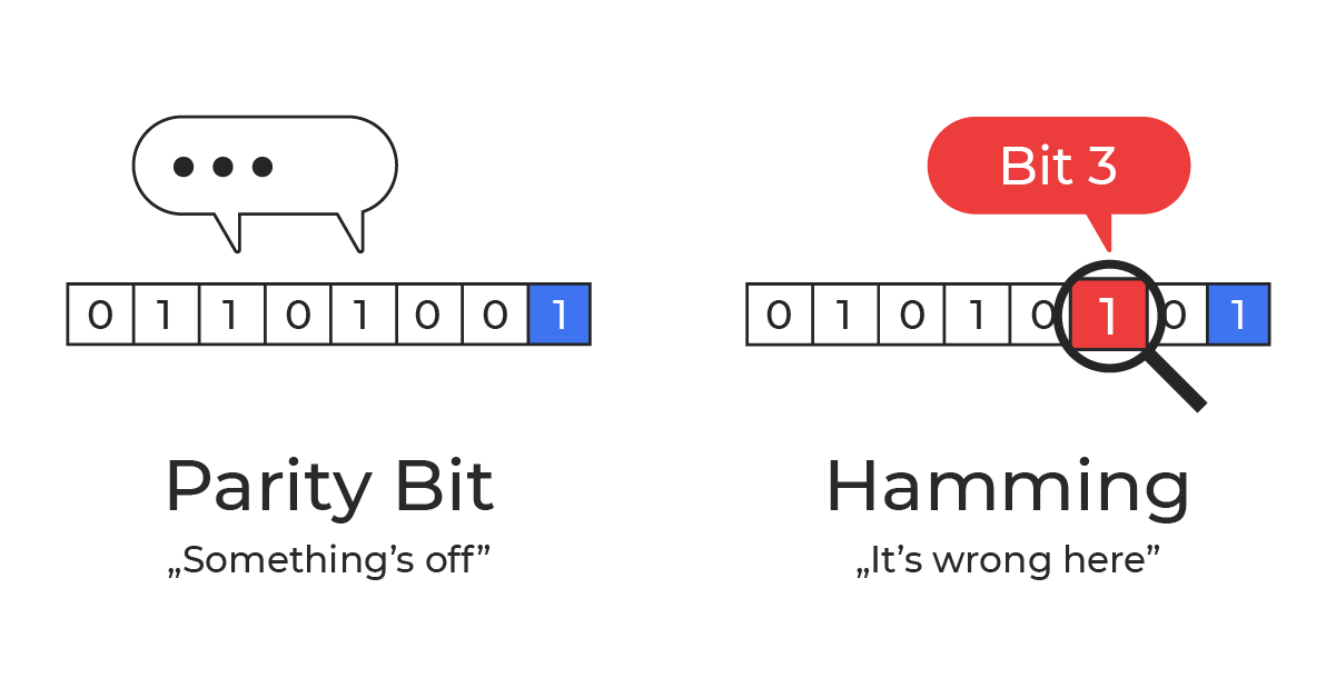
The Hamming code was invented by Richard W. Hamming in the late 1940s. At the time, he was working at Bell Labs. He grew frustrated with early punched‑card computing workflows where a single flipped (or misread) bit could cancel an entire run, wasting hours of machine time and operator effort. The method of error detection using a parity bit was already known at that time. The problem was that it would simply interrupt the work, whereas it could have been corrected instead.
As he wrote in his book “The Art of Doing Science and Engineering – Learning to Learn” :
“Error detection of a single error is easy. To a block of (n–1) bits we attach an n-th bit which is set so that the total n bits has an even number of 1’s (an odd number if you prefer, but we will stick to an even number in the theory). It is called an even (odd) parity check, or more simply a parity check.”
It was this ordinary engineering frustration that led him to start thinking about a method to safeguard the data – not just detecting that something went wrong, but also correcting it.
He began with a straightforward idea: arrange bits in a table and add parity checks for both rows and columns. With one error, the “bad” row and the “bad” column intersect at the exact bit that flipped.
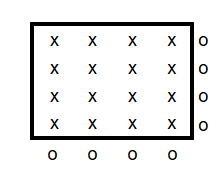
For example, take a 4×4 array holding 16 data bits. If you add a parity bit for each of the 4 rows and 4 columns, you need 8 extra bits to locate a single error. For an 8×8 grid (64 data bits), you’d need 16 parity bits. It works, but it’s wasteful and scales poorly.
Hamming’s final solution was far more elegant: it locates (and corrects) a single-bit error with far fewer check bits.
Hamming Code – Solution
Data encoded with a Hamming code is protected against a single‑bit error. If one bit flips, you can find it and correct it using only a few extra bits.
For 64 data bits you need 7 parity bits (8 with double-error detection). For 128 data bits you need 8 (9 with double-error detection). Each extra parity bit roughly doubles the maximum block length.
In general: for m data bits you add r parity bits. r is the smallest number that satisfies:
2^r ≥ m + r + 1
Of course, with a longer block, the chance for an error increases, so the length of the block has to be adjusted to your needs.
Ok, but how is it done?
The whole “magic” is just smart placement of parity bits and a clear rule for what each one checks.
Example
The easiest way to explain this is with a concrete example.
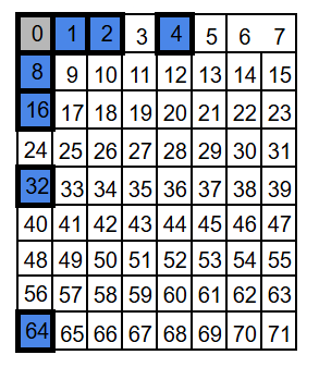
Let’s start with a block of 71 bits. We number positions starting at 1 (not 0), because then the parity positions land on powers of two: 1, 2, 4, 8, 16, 32, and 64. These are the parity-check bits. All other positions carry data bits (64 of them).
For visualization we’ll draw it as a 9×8 grid (72 slots) and leave one slot empty – the exact shape doesn’t matter, but a compact grid is nicer to look at.
If you’re a programmer, your first instinct might be to put all the integrity (parity) bits at the end of the block, not sprinkled inside. It feels cleaner, and it looks like it would make the calculations easier. The catch is: Hamming codes use the bit position as part of the math, so those parity bits need to sit at specific power-of-two positions – exactly what you want if you’re building a decoder for a relay machine like Bell Labs’ Model 5 in the 1940s: simple, regular wiring and straightforward logic. Still, the basic idea is the same either way: compute parity checks and use them to detect (and locate) an error.
Each parity bit covers about half of the data positions — just in a different pattern. If the number of 1s in a given group of data bits is even, the parity bit is set to 0; if it’s odd, the parity bit is set to 1. Another way to think about it: the parity bit is chosen so that the total number of 1s in the group (data + parity) is always even. Parity is a bit… obsessive-compulsive about one thing: the number of 1s has to be even.
Because XOR over an even number of 1s evaluates to 0 (and over an odd number of 1s evaluates to 1), we get a simple rule:
- Encoding: the parity bit equals the XOR of all data bits in its group.
- Decoding: the XOR of all bits in that group (including the parity bit) should be 0.
Let’s look at the parity groups. We have seven parity bits, so we have seven parity groups – one for each parity bit. We will call them by their “address”: P1, P2, P4, P8, P16, P32, and P64.
Each group starts with its own parity bit and then follows the same “take/skip” pattern. For a parity bit at positio
P1: take 1, skip 1 (every other position)
P2: take 2, skip 2
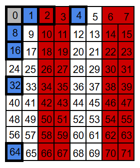
P4: take 4, skip 4
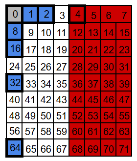
P8: take 8, skip 8
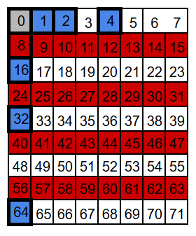
P16: take 16, skip 16
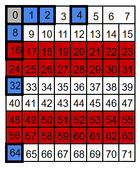
P32: take 32, skip 32
P64: take 64, skip 64
Notice what happens with P64: in theory it would take the next 64 positions, but our block ends at 71, so this group only reaches positions 64-71.
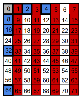
We arrange the bits into seven overlapping groups so that every position has a unique membership pattern. When a single bit flips, only the parity checks for the groups that include that position can change – some will fail, the rest will still pass.
For example, position 3 belongs to groups P1 and P2 (and to no other parity group). So a flip at position 3 can only affect the P1 and P2 checks. Any other position that belongs to both P1 and P2 will also belong to at least one more group – for instance 7 belongs to P1, P2, and P4; and 11 belongs to P1, P2, and P8.
That’s because the set of parity groups for a position is encoded in the binary form of its address. Take this bit nr 3 as an example: 3 = 0b011.
- P1 covers all positions whose binary address has a 1 in the least significant bit – so 3 is included (0b011 ends with 1).
- P2 covers all positions whose binary address has a 1 in the second least significant bit – so 3 is included (0b011 has the second bit set).
- P4 covers all positions whose binary address has a 1 in the 3rd place – so 3 is not included (0b011 has no 4’s bit).
- P8 covers all positions whose binary address has a 1 in the 4th place – and so on.
Data bits can belong to at least two parity groups – the number of groups is simply the number of 1s in the binary address of the position. Parity bits sit at power-of-two positions (1, 2, 4, 8, …), so their addresses contain exactly one 1.
Hamming code in action
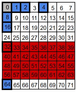
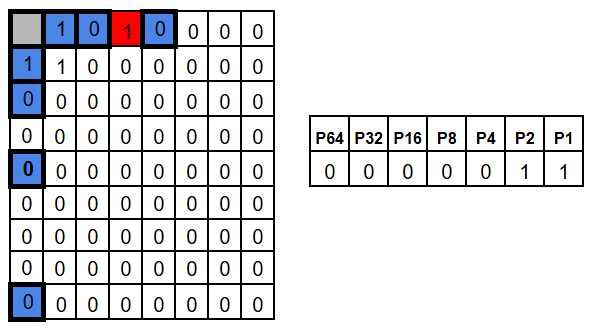
Now let’s see this in action. We’ll take a real 71-bit block, fill in the 64 data bits, and compute the seven parity bits (P1, P2, P4, …). For the sake of easy computation, we’ll set all data bits to 0 – except position 9, which we set to 1. Since bit number 9 belongs to both the P1 and P8 groups, the corresponding parity bits need to be set accordingly, so that each of these groups has an even number of 1s.
In the following diagrams, the parity bits are highlighted in blue, for readability.
This is what our encoded frame looks like – and that’s it. That’s all there is to do.
On the decoding side (for example after transmission) we recompute the parity for each parity group (this time including the parity bit as well). The result is 7 bits of parity check: one parity bit for each parity group.
We can arrange them in a 7 bit sequence, where P1 parity bit is the least significant bit, then P2, P4, P8, P16, P32, and P64. This 7 bit value is shown on the right side of pictures below, together with their parity group names.
Since we didn’t introduce any error in our bits, it’s no surprise that the parity of each group is even, so all the results are zeros.
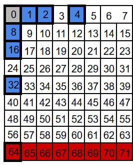
Now let’s introduce an error by flipping position 3. The groups that include position 3 – P1 and P2 – now have odd parity.
As a result, the check results for P1 and P2 become 1, while all the other check results stay 0. In other words, we get 0b0000011, which points to bit 3.
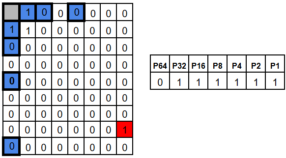
A flip in a different position produces obviously a different pattern. For example, position 63 belongs to every parity group except P64, so flipping it would make P1, P2, P4, P8, P16, and P32 fail, while bit P64 still is 0.
The results of the parity checks is a vector called the syndrome. Hamming chose the checks in a way the syndrome doesn’t just say “an error happened” – it tells you the exact address of the flipped bit.
If the whole block has length N, then there are N possible single-bit errors plus one “no error” case – N+1 cases to distinguish. Since r parity checks produce 2^r possible outcomes the rule 2^r ≥ m + r + 1 becomes obvious.
So, at the end of the day, you need only to swap the bit that syndrome points to and you have restored original data.
SECDED – Single Error Correction, Double Error Detection
With plain Hamming (SEC), the syndrome is perfect for one flipped bit. But with two flipped bits, the syndrome no longer points to “the error” in a meaningful way. It’s shown in the picture below, where both above example errors occurred at once.
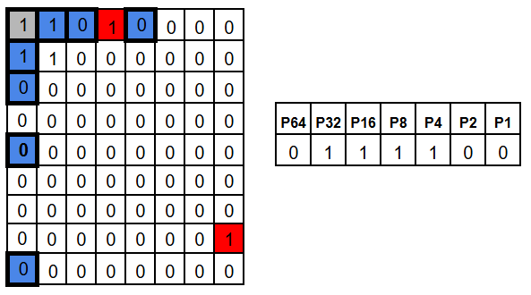
In that case the syndrome for two errors is basically the XOR-combination of two single-error syndromes. That combined value looks like a valid address – so the decoder may “correct” the wrong bit, turning a two-bit error into a three-bit error. Not ideal.
The fix is simple: add one more parity bit over the entire codeword (an overall parity bit). This gives us one extra piece of information. Single error will cause this entire area parity check to fail, while double error not.
So:
- non-zero syndrome + overall parity fails -> a single-bit error (safe to correct)
- non-zero syndrome + overall parity passes -> a double-bit error (impossible to correct)
This is exactly what SECDED means: we still correct any single-bit error automatically, but we can also reliably detect (and refuse to “mis-correct”) a double-bit error.
Matrix way
At the end, if you’re feeling brave, you can play with Hamming encoding as matrix multiplication.
Here’s an example.
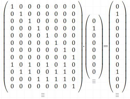
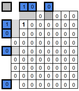
The second matrix is our data – 0b01000000. The first matrix has two parts: an identity block on top that copies the data bits, and a coding block at the bottom where each row selects the bits for one parity check. This example keeps the parity bits at the end of the result rather than at power-of-two positions – the math works anyway. Our output is: 8 bits of input data, and 4 bits of parity check.
If you do this as regular matrix multiplication, not binary, each parity row gives you the count of 1s in its group. Reduce that modulo 2 and you get the parity bits – even count is 0, odd count is 1. That’s the only twist compared to normal matrix math.
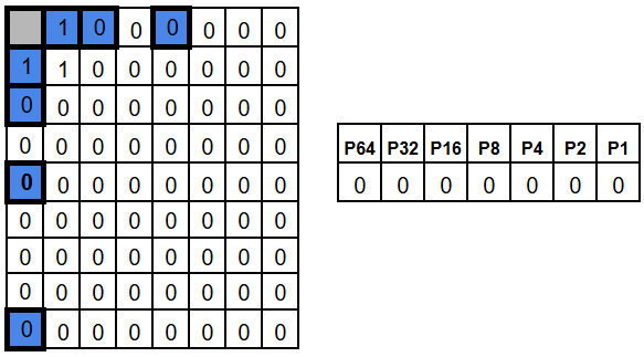
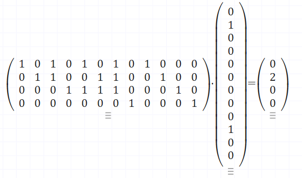
Decoding is also a multiplication. This time the first matrix defines the parity checks, and the second is the encoded data. After reducing modulo 2, the output bits are the check result – the syndrome. Again all zeros means no error, otherwise, the pattern tells you which bit to flip. Since this example uses a slightly different layout, the syndrome won’t be a straight binary address anymore. Here, the “error address” is defined by the columns of the parity-check part of the matrix – in our case they’re simply numbered 1, 2, 3, 4.
In case of no error – output modulo 2 is [0 0 0 0]
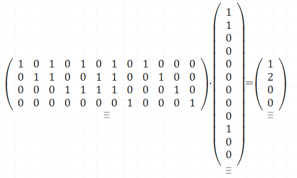
In case of error on first bit – output modulo 2 is [1 0 0 0]
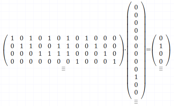
And here in case of error on second bit – – output modulo 2 is [0 1 0 0]
I encourage you to play with this on matrixcalc.org a bit.
